RF Dropper Box
Motivation.
I teach high school physics and engineering and was looking for a way to drop items from a high up place for things like egg drop challenges. My school lacks balconies and I didn’t want to bother with the hassle of climbing up a ladder to the roof, so I started to design a device that could be loaded up, then pulled up into the rafters of the our metal shop and released remotely.
I first designed a device that used 8 small solenoids to hold light weight objects like parachute men. The dropper was run with a Raspberry Pi Zero and a separate controller box was run with and Arduino MKRZero board. When buttons were pressed the controller, it would send text commands to the and attached laptop that was connected to the Pi through SSH. The Pi, running a Python program, would receive the commands and respond accordingly. This project was a good learning experience, but had a number of drawbacks, including the complexity of setting up the communication between the controller and dropper and the weight of the payload that the solenoids could hold.
I knew I had an up coming unit in my AP Physics class that involved designing and building a device to safely drop 4 eggs from a large drop, so I made this, larger, stronger, and more easily controlled dropper.
Process.
Dropper Box design
The box is made from laser cut, quarter inch birch plywood. Even though it is a simple cube, I used MakerCase to create the DXF for the parts. The box is held together with wood glue, but I made some extra brackets for support and convenient hanging. These were designed in Fusion 360 and printed on a Prusa MK3s. The hinges are bought at the local hardware store, as was the stock aluminum bar that fits into the latch. The rubber feet on the bottom were extra parts I had laying around from a cooling fan I used in a different project. I also designed and printed a holder for the battery pack that included a face for mounting the relay and wire connections. The battery pack is 12V, which is what was needed for the powerful solenoid, but it also included a 5V USB connection, which I used to power the Arduino.
Latch design
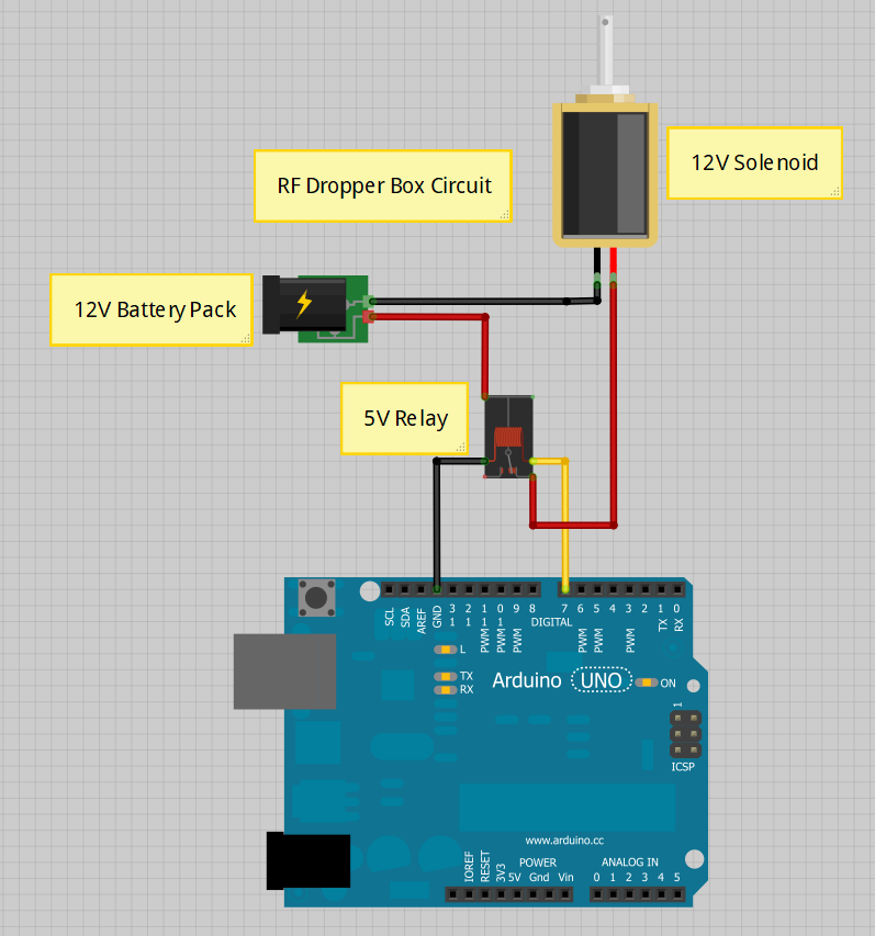
Figuring out a powerful way to open the trapdoor, even when a large mass was pressing on it, was one of my favorite parts of this project. I originally thought about using a stepper motor, but got a headache trying to design ways to mechanically increase the torque while generating enough range of motion to open a latch. Next I looked at solenoids, which are one of my favorite output components in my projects. I usually use small, 5V solenoids, which don’t have much push/pull power. I decided to splurge and get a large 12V solenoid off Amazon for $16 and was not disappointed. As you can see in the video above, I created a two part housing for it that included a lever arm. This increased the range of motion at a small decrease in strength, but I have yet to encounter a payload on the trap door that the solenoid can’t overpower. Thankfully the 12V that I’m using for the solenoid and Arduino (through a regulated 5V USB output) handles the quick spike in current and doesn’t crash the Arduino. To be safe, I still tried to mount the Arduino and RF module as far from the solenoid and 12V lines as possible.
Controller design and electronics
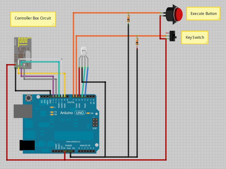
The controller box contained an Arduino Uno and nRF24L01 module that served as a transmitter. I also included an RGB LED to indicate the state of the controller (green for unarmed or safe, red for armed, and blue when the execute button was pressed and a signal was sent). I used a bit of green PCB to help wire the pull down resistors, mount the LED, and connect the button and key switch to the Arduino. I decided to include the two blue screw terminals for connecting the switch and button.
The box itself has also designed in MakerCase and laser cut out of 5mm acrylic, then glued together. The bottom is held on with screws, so it can be opened easily for maintenance. The Arduino could have been powered by an internal battery pack, but I decided to route a USB cable out of the box so I wouldn’t have to open and close the box too often, even if it makes the design look a little less polished.
Dropper electronics
The Arduino Uno on the dropper box had a nRF24L01 transceiver module on it as well, wired the same as the transmitter in the controller box. I omitted that in the schematic below. This circuit was soldered to PCB and mounted to the front of the 3D printed battery pack holder. I included some screw terminals for the wire connections so it would be easier to assemble and repair the final product.
Code.
This is the code for the transmitter (controller box):
This is the code for the receiver (dropper box):


