Kinetic Sand Table
Motivation
Like many of you that have found your way to this page, I stumbled across a mesmerizing video of the Sisyphus Sand Table a few years back. I was intrigued by what I saw and made a mental note to one day reverse engineer how it worked.
As the 2020 pandemic lockdowns continued to drag on, I found I was scrapping the bottom of my project idea barrel and finally set out to tackle this challenge.
One of the goals I set for myself was to not use anything besides the video above for inspiration, so I didn’t google to see if anyone else had tried this yet. After a few months, when I had my sculpture drawing interesting patterns, I finally relaxed my rule and looked at what else existed out there in the internet. I found this video by RCLifeOn, which took a very different approach (cartesian coordinates versus my polar coordinates), but made me aware of the awesome g-code generating website Sandify. I rewrote my entire code to work with the Sandify files and it helped take my project to a new level of satisfaction.
Until I make a better video describing some of the specifics of the design and construction, this 90 second demo reel shows my project at a few stages in its development:
Process
As an up front disclaimer, this is not a step-by-step “how to” tutorial. I’ve tried to provide enough insights, diagrams, pictures, code, and “lessons learned” that a motivated maker would be able to recreate my project, but still with some enjoyable challenges along the way.
I love troubleshooting problems, so don’t hesitate to reach out to me if you have any questions.
Initial Decisions
Electronics
As is clear to most people, the whole operation hinges of being able to move a magnet around in a complex pattern under a table covered with fine sand. I knew the complexity of these movements would be more than a microcontroller alone could do, at least for more than the most basic shapes. I decided I would either use a RaspberryPi, or have an Arduino directly connected to an operating computer. Because it’s always nicer to have a wireless final project, I decided to go with the former.
For motion, I knew I’d be working with stepper motors, so I ordered a few variations to experiment with and some motor controllers.
Magnets
Next, I experimented with different combinations of magnets to find ones that were strong and small. I also did plenty of tests with potential materials for the table top, since I didn’t want to get too far along, only to find my table surface was too thick to keep a strong magnetic attraction between the upper and lower magnets. I initially settled on a cylindrical neodymium magnet for underneath (10mm in diameter and 3mm tall) paired with a 20mm spherical magnet for the top. These would be separated by 3mm frosted acrylic, which I could cut on a laser cutter. Testing this combination by moving the magnets with my hands left me confident they would work. Later in my project, after adding sand, I found that the 20mm spherical magnet tried to ride above the sand more than plow through it, so I replaced it with a much smaller 5mm spherical magnet (like the ones that were a popular toy a few years back, until a bunch of kids ate them and got sent to the hospital for kinking up their insides).

Polar versus Cartesian
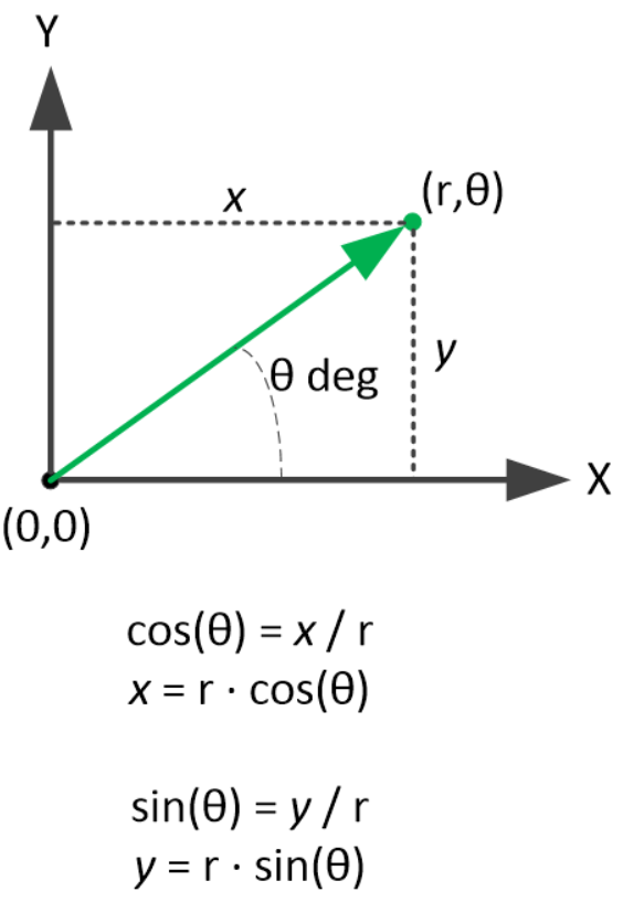
One of the first big decisions in my planning phase was whether to control the bottom magnet with a system that worked in polar coordinates (one motor to rotate the angle theta, a second to change the radius) or cartesian coordinates (a motor for each of the x- and y-axes). From my experience with 3D printers and CNC machines, I felt the cartesian plan would be more intuitive, but ended up going with the polar coordinates. One reason was that it was a new challenge (and an excuse to apply math skills that I hadn’t used since college) and the other was that it would allow for a smaller footprint of the sculpture. I wanted the drawing area to be circular, which meant that if I used cartesian coordinates, I’d either have a bunch of undrawn sand around the interesting art, or I would need a large case to hid the ends of the x and y gantries.
Also, at this early point in my project, I assumed it would be easiest to create interesting patterns in polar coordinates by slowly evolving functions of theta and radius, such as the “Polar Rose,” cardioids, and lemniscates.

Eventually I wanted to be able to do more complicated patterns, but knew these would probably require g-code and couldn’t figure out how to generate the g-code in the first place. Towards the end of my project, after discovering the website Sandify, I went back and rewrote my program to interpret g-code.
The Build
Bill of Materials
Click here for an Excel spread sheet of the products I used in this project.
The spread sheet contains the items I used, an approximate quantity, description of the use, and links to where I purchased them (or similar).
Mechanical Motion

The mechanical portion of the project can be considered in two parts that had to work together, which I ended up calling the “rotor” and the “rail.” The rotor is the part that spins the assembly around in circles and included a NEMA 17 bipolar stepper motor, GT2 belt, a 16 tooth and 60 pulley (smaller on the motor shaft, large on the main shaft), an 8mm diameter metal rod (main shaft), and a pillow block bearing. The rail is the part being spun around by the rotor and determines the radial position of the magnet. It included a metal linear rail with shuttle, GT2 timing belt, idler pulleys, and a NEMA 11 bipolar stepper motor with a 16 tooth pulley on the shaft.
In addition to the hardware mentioned above, which were mostly ordered off Amazon, the white parts were designed in Fusion 360 and 3D printed on my Prusa MK3s with PLA filament. There’s also a bunch of random metric bolts, nuts, and washers (mostly M3) as well as some miscellaneous circuitry and wires.
The connection point between these two points, which I’ll call the main rotation shaft, was one of my favorite challenges of the build. With the use of conductive tape, spring tensioners, and 3D printed parts, it transfers electricity to the four wires of the rail stepper motor while allowing the rotor to make an endless number of rotations without getting twisted in wires.
Rotor
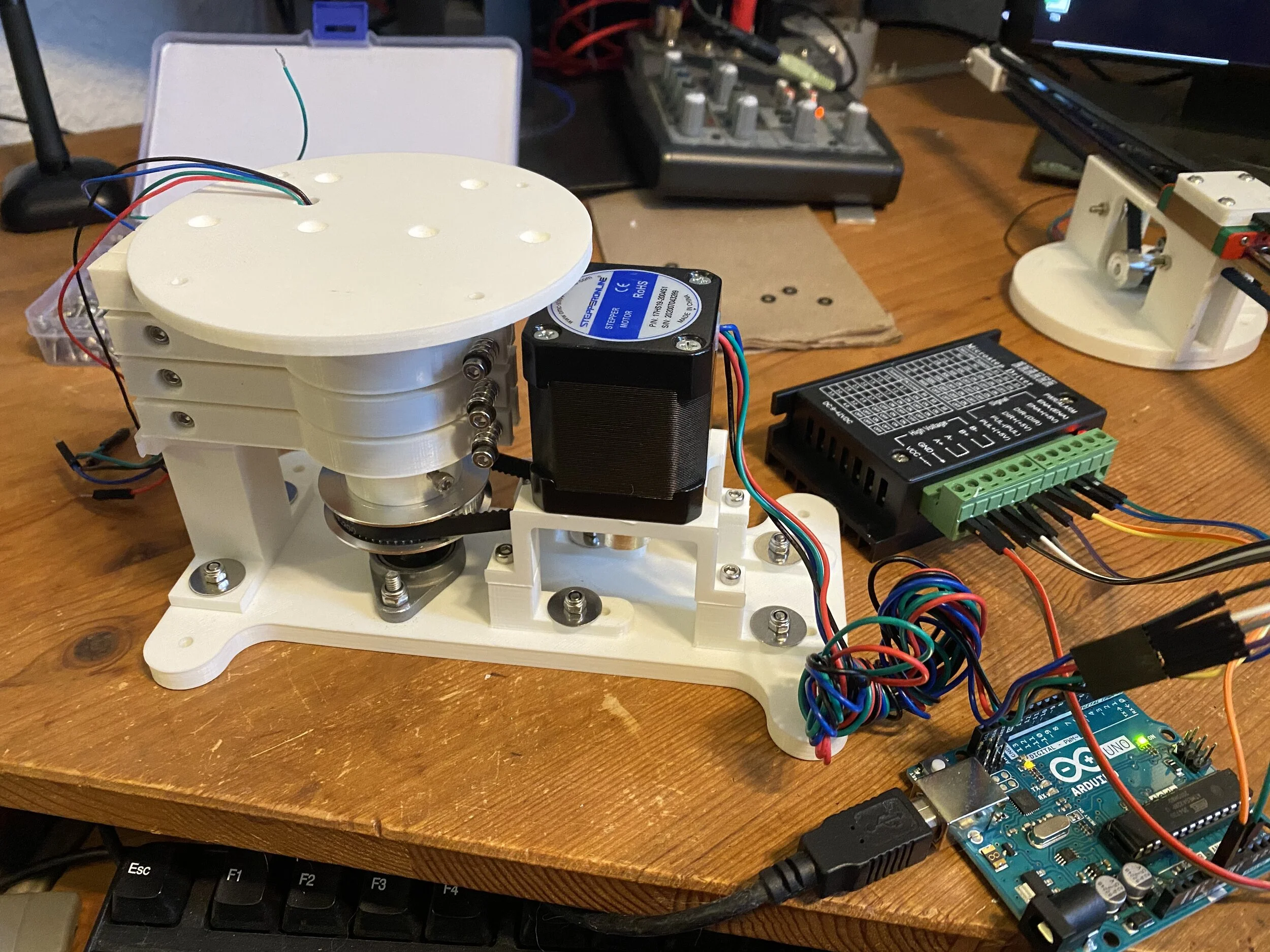
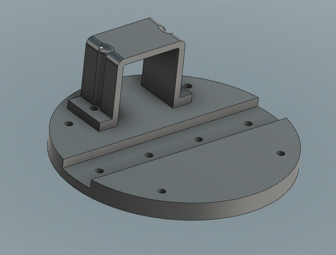
The lower portion (shown with the main rotation shaft installed above, and an Arduino for testing purposes) served to mount the motion assembly to the inside of the case and rotate the rail above it. The base had four holes in the corners to bolt it to the bottom of the enclosure. The stand for the inverted stepper motor is made of 6 separate parts, due to the constraints of 3D printing parts with overhangs. Two parts attach directly to the motor and the other four parts are the feet, which attach to the base. These feet have slots under the washers so that the tension of the GT2 belt could be adjusted.
To the left of the stepper motor is the main rotation shaft. The main shaft is a 8mm steel rod which I had on hand from a different project. I cut it down to size with a hacksaw. The shaft is seated in a pillow block bearing, which is secured with a set screw and bolted to the base. The bearing had a little play, so it took some work to get it perfectly flat.
The output shaft of the stepper motor and main rotation shaft are connected with a GT2 belt and pulleys. The motor pulley has 20 teeth and the rotation shaft has 60, which gives a gear ratio of 3:1. In other words, the motor needs to spin three times to rotate the main shaft once. This had the benefit of allowing me to run the motor in full steps (more torque) without too much sacrifice to the angular resolution. It also increased the torque on the main shaft, allowing it to overcome the extra friction created by the electrical contacts assembly.
Rail


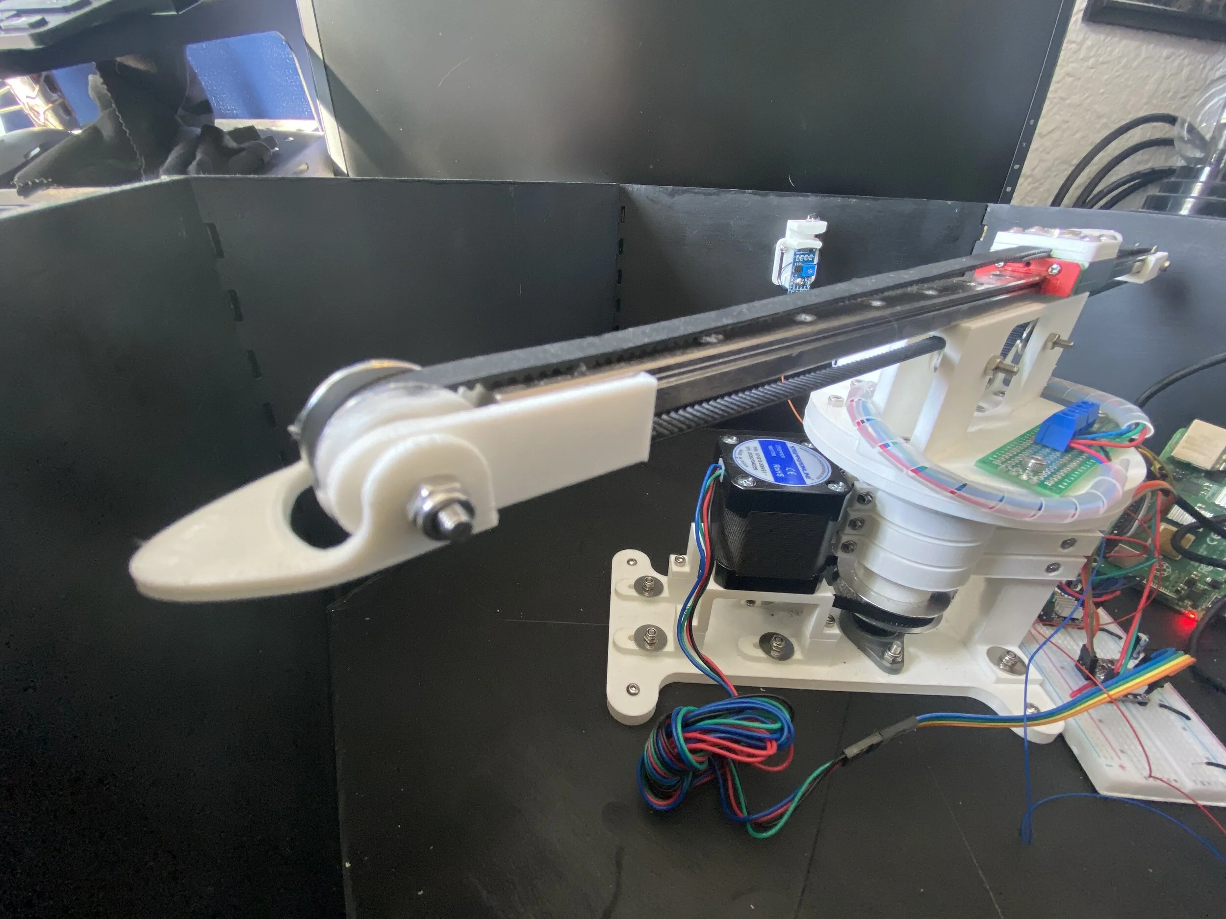
The rail is the portion that moves the shuttle (with attached magnet) radially. It has a matching, round base that bolts to the matching platform of the rotor mechanism. The main metallic portion is a 350 mm long MGN12 linear rail with carriage block that slides smoothly on internal bearings. I got it off Amazon, where it was marketed for DIY 3D printer builds. It has a variety of holes on the rail and shuttle that work with M3 bolts.
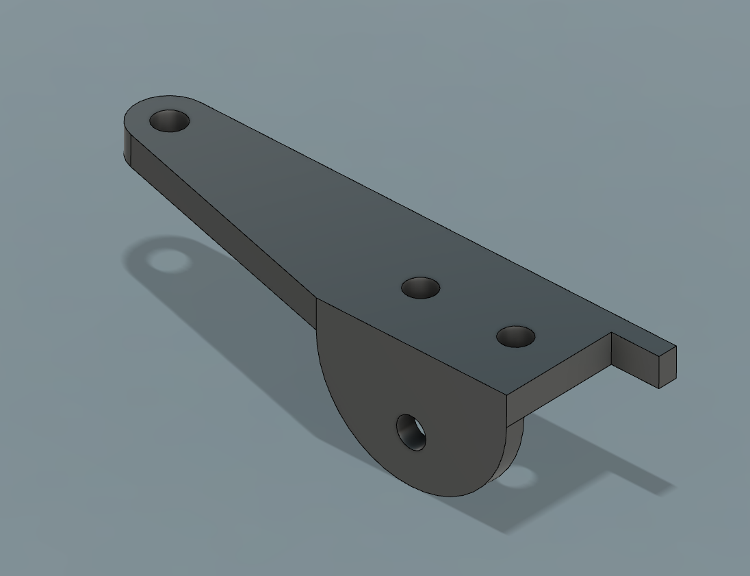
To move the shuttle back and forth I used GT2 timing belt, which is pretty common for 3D printers. The ends of the belt are sandwiched between the two 3D printed components on top of the shuttle, where I also glued my cylindrical magnet. The belt runs over the ends of the rail on two 20-tooth GT2 idler pullies with a 3mm internal bore. These pulleys are held in place with 3D printed mounts. On one end is an additional “finger,” added later, which is used to trip a light sensor for position homing.
Everything mentioned above is mounted on a two-part, hollow tower. These two tower parts are symmetrical, so when flipped around they appear to be one piece, with the stepper pointing into the central opening. These were printed in two parts to avoid using any supports for overhangs. In the first picture you can see an earlier iteration where the two tensioning, smooth idler pulleys were outside the tower and attached directly to the underside of the metallic rail. This didn’t tension the belt adequately and some slippage at the stepper motor pulley was occurring, so I moved them inwards. You can see in the later pictures that the idler pulleys are inside the tower and form a tighter V around the stepper motor.
Initially the stepper motor was a cute NEMA 8 that I had left over from my self-playing tremoloa project, but I remembered the reason I had it left over is that the torque is poor. It struggled to move the belt, especially when the shuttle reached the ends of the rail and the belt formed a bit of an angle, so I swapped it out with a NEMA 11. Thankfully this only required me to redo the hold down strap that goes over the top of the motor.
The bottom of the tower bolts to the round base with 4 short M3 bolts. That round base is then bolted to the matching plate on the main rotation shaft with 4 more M3 bolts. There is a matching hole in both plates to route the wires from the rail stepper motor down to the inside of the main rotation shaft, where they connect to the copper bands. For a cleaner look, it would have been possible to have these wires be one long run, but in the spirit of modularity and ease of repair, I added the green circuit board with screw terminals so I could remove the whole rail portion from the main rotation shaft without cutting any wires. The circuit board is simply held in place by sharing two of the four bolts that attach the rail component to the main rotation shaft.


Main Rotation Shaft


The heart of the main rotation shaft is a stainless steel rod, 8 mm in diameter and about 100 mm in length. The length of this rod didn’t need to be too precise, since I left a hole in the base to pass through, and there was extra room in the upper 3D printed part. This rod was one of two guide rails included in a linear rail kit that used an acme screw. I’d originally planned to use this for the main part of the rail, but it was bulky and didn’t get the shuttle as close to the ends of the rail as I wanted. I used a hack saw to cut it down to the length I needed.
The lower end of the steel shaft is mounted in a pillow block bearing via a set screw. The upper end extends far into a 3D printed component that can be seen in the pictures above and was held in place with another set screw. This component, which rotates with the steel rod, had a flat top to mount the rail portion of the assembly and is one half of the mechanism that transferred electricity between the rail stepper motor and the RaspberryPi.
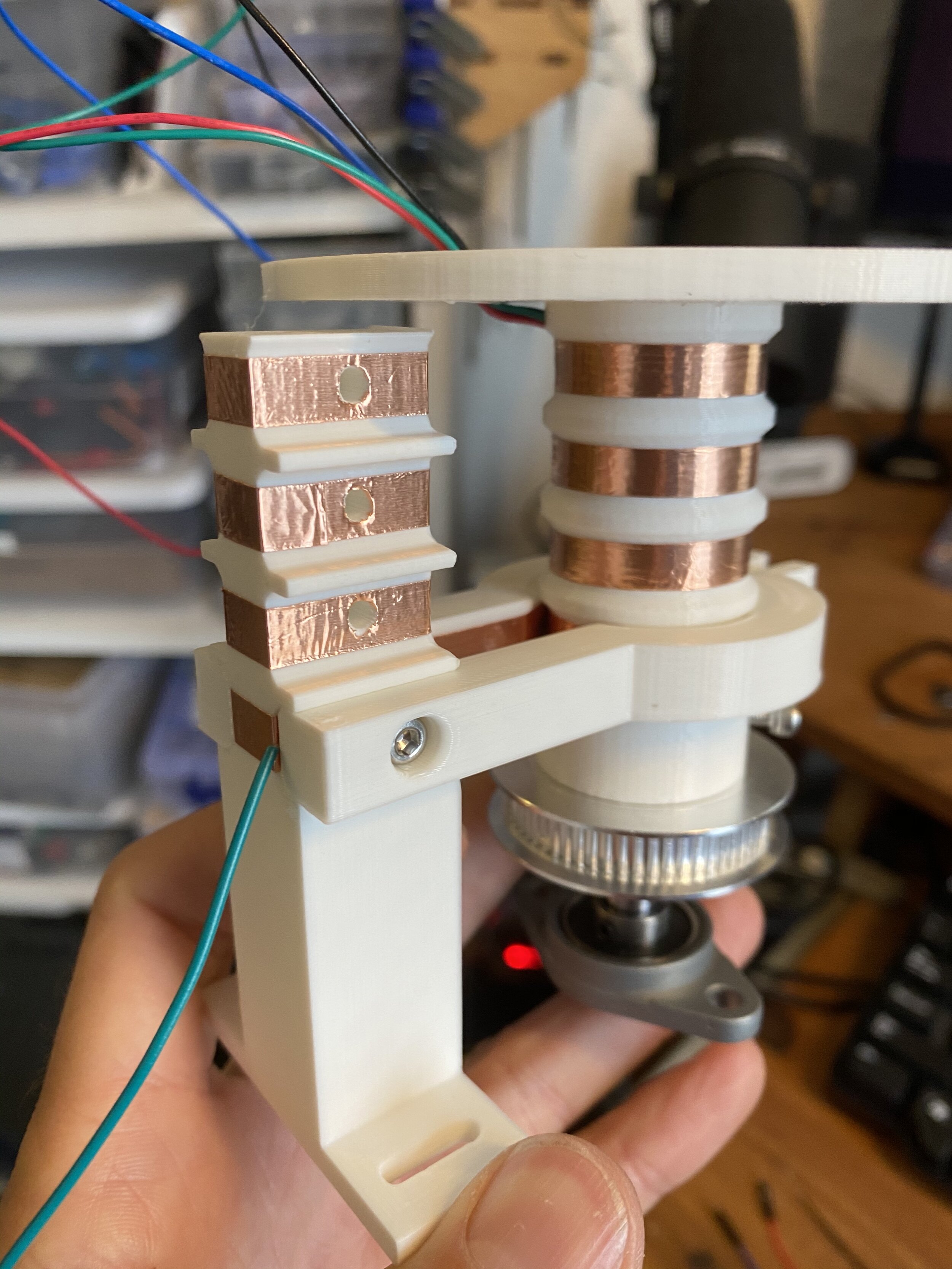
You can see in the pictures above that four wires from the top of the platform (the wires that will eventually connect to the bipolar rail stepper motor) sneak underneath into a hollow channel. The channel has four openings, one for each of the grooves that circumscribe the diameter. I pulled one wire through each of these holes, stripped them of their insulation, then taped over with with copper conductive tape.
The other half of this electrical transfer system was stationary and bolted to the main base. It consisted of a tower with four pairs of arms extending out at intervals matching the grooves on the rotating portion. You can see in the photos that the contact surfaces were also covered with copper conductive tape. On the tower side, a stripped wire was wound around the bolt as these arms were installed. At the other end of the arms, after they have wrapped around the rotation shaft, tensioner were added to each arm pair, each comprised of a bolt, nut, spring and washer. This allowed me to fine tune the tension of each arm pair, ensuring good electrical contact without creating too much friction.


Enclosure


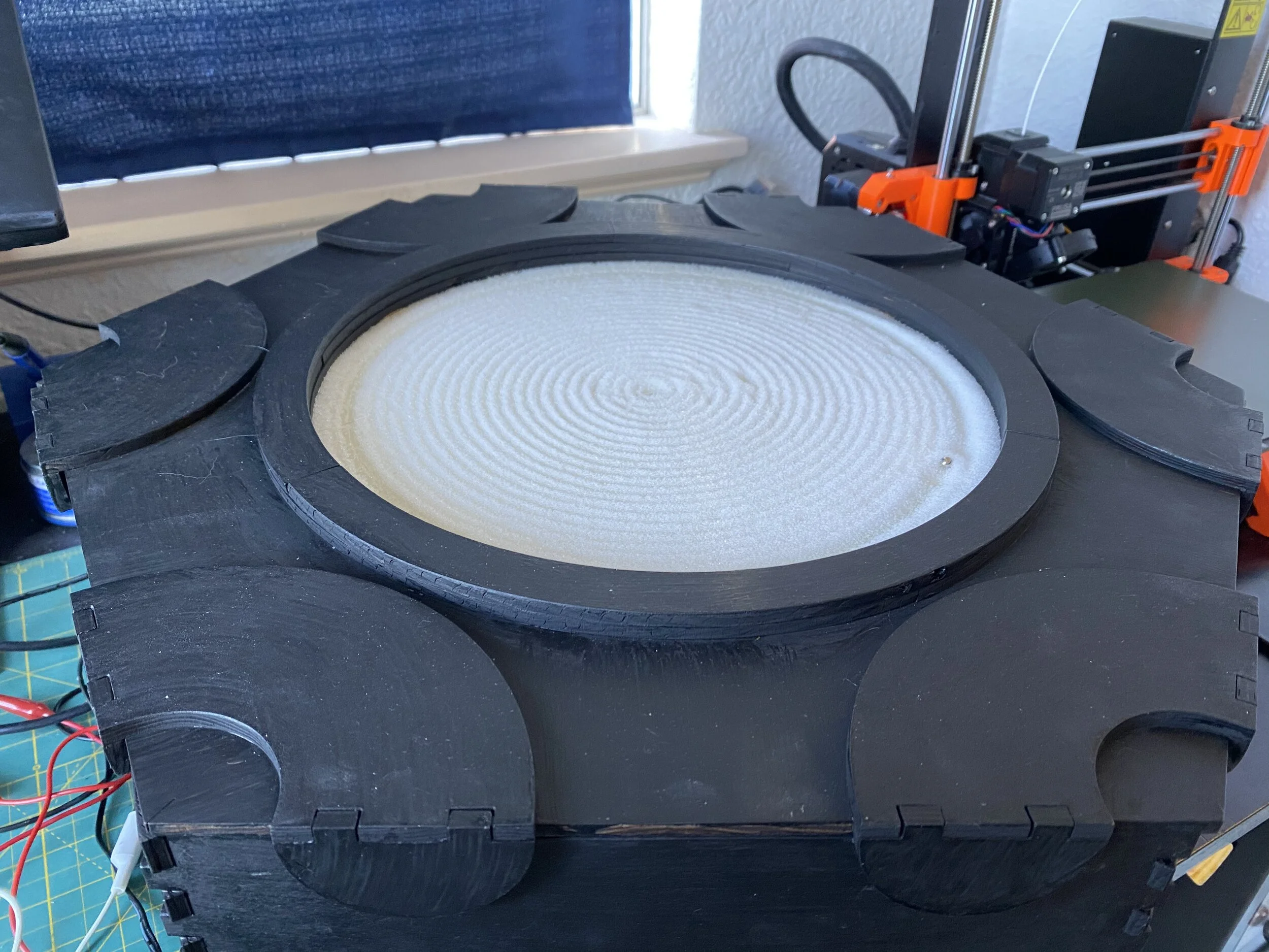
I would have enjoyed a round enclosure that more closely fit the motion assembly, but what I had at my disposal was a laser cutter and 1/4” plywood, so I went for something a bit clunkier and geometric.
I started by using the fabulous website MakerCase to create a hexagonal box with flanged joints that met my height and width requirements. The top and bottom of the case were too large for the bed of my laser cutter (a BOSS LS-1420, also a brand I’d recommend), so I used Adobe Illustrator to modify the SVG layout. I sliced these large portions into thirds (convenient with a hexagon), which brought them down to a size I could work with. It also had the added benefit of marking the center of my base, helpful when later installing the motion assembly. While I was working in Illustrator I also cut out the circle in the top and removed the flanges that would attach the top to the base. In the final form, the top is just resting on the bottom of the box, but is centered by the 12 semicircles that drape down over the sides.
I usually love the look of unfinished birch, but thought some black paint might help the white sand ‘pop.’ The paint needs some touch ups, and if I did it again, I’d probably stick with the unfinished birch to emphasize that DIY look.
I did laser cut a clear acrylic circle to cover the sand, but regardless of what type of sand I used, there was a strong electrostatic attraction between the two. Currently I just leave it uncovered (my cats have only jumped in it once), but in the future I may try increasing the height of the cover or experimenting with glass to see if it holds a little less charge.
Position Sensors
In order to prevent having to open the box and reset the motion assembly to some starting position each time the sculpture was turned on, I tried a number of different methods for “homing” the rail and rotor. This was one of the greater challenges of the project and I’ll describe some of my failures, current solution, and thoughts for future improvements.
Consideration of the need for homing came late in my design process. In retrospect I would have preferred if these feedback mechanisms were integrated into the main motion assembly. For example, a limit switch attached to the rail that would be pressed when the shuttle reached the end and another switch that would be pressed each time the main rotation shaft passed a certain point. To avoid major redesigns I instead explored solutions that mounted to the inside of the case.
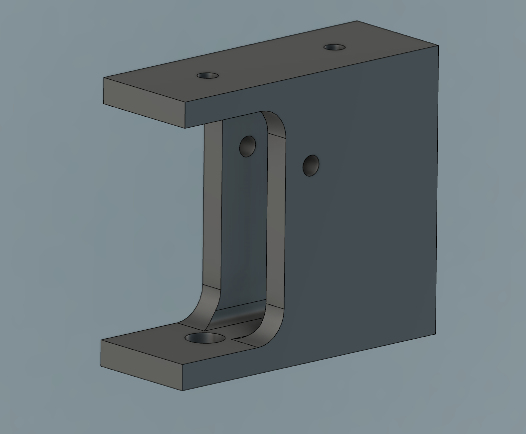
My first solution was very mechanical. I 3D printed a two part mechanism that held a limit switch and facilitated its triggering. One of these devices was mounted on the inside of the case at the level of the rail and another was mounted across the case on the opposite wall. I created a “bumper” extension for one end of the rail that would only touch one of the switches, and added an extending point to the rail shuttle, which would only trigger the other switch if the shuttle was at the end of the rail. While this design worked as intended, it had the huge draw back of making a noise as the rail bumper slide across and then clicked the limit switch with every single rotation. These small noises were amplified by the resonating chamber of the enclosure and really distracted from the Zen aspect of the project.
Next I explored using Hall effect sensors and magnets. If you are unfamiliar with the Hall effect, it’s essentially a measurable change in voltage that occurs across a plate when a small current running through it is exposed to a magnetic field. The biggest challenge with this is that it requires an analog input to read the changing voltage level, which a RaspberryPi does not have. You can use an analog to digital converter to accomplish this communication, but I just used an Arduino Uno that I had on hand to read the Hall effect sensor, then sent that data to the Raspberry Pi over a serial connection. After all that work I found I was unable to get the motion assembly to stop precisely with any reliability.
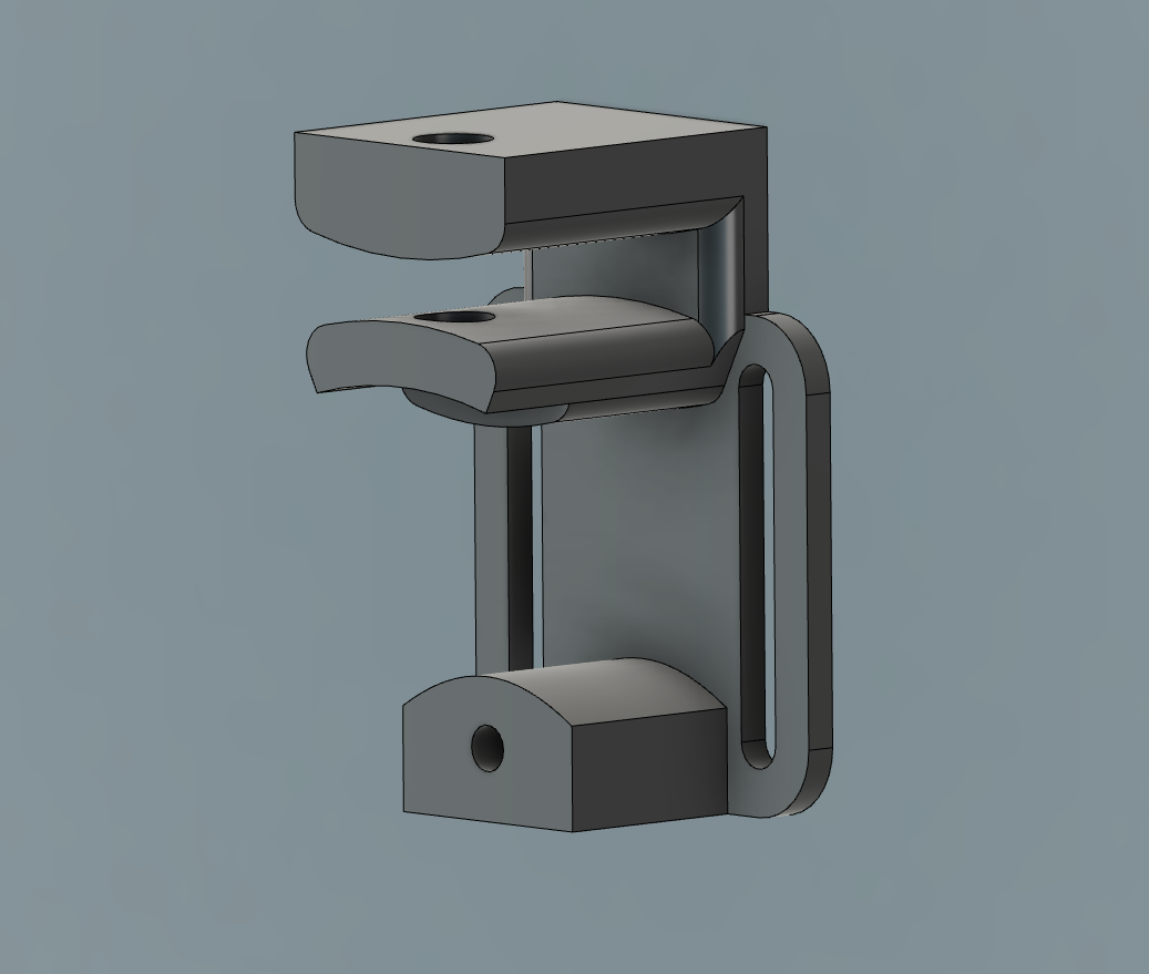
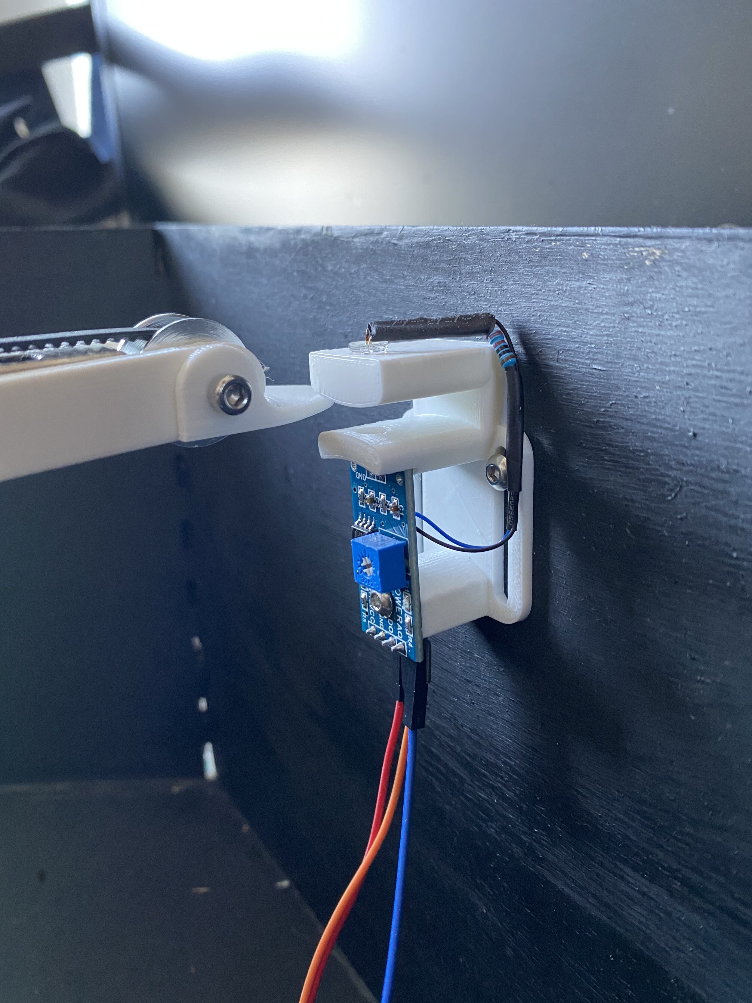
Finally I settled on a combination of my original, mechanical method for the rail and an optical sensor for the rotor. I designed and 3D printed a mount for the side of the box that pointed an LED directly at a light sensor module. This module can provide analog voltage readings of the photoresistor, or can output a digital signal when the reading of the photoresistor crosses a threshold set by a small trim potentiometer on the module (which is what I used). To trigger the light sensor, I replaced the bumper on the end of the rail with a thin “finger” that would pass between the LED and light sensor, causing it to trigger. This was able to home the rotor with excellent consistency. I kept the same basic, mechanically homing mechanism for the rail (a limiter switch on the wall of the enclosure that is triggered by a pointer on one side of the shuttle), but redesigned it to have a lower profile so it wouldn’t collide with the finger on the rail. It does still get triggered erroneously on occasion making some noise, but only when the rail as at its maximum extent and the rotor is in a particular position, so not that often.
In the future, I might replace the rail homing mechanism with something attached to the 3D printed part of the rail. Once reason I thought I couldn’t do this initially was that it would also need a complicated solution for transferring electricity to the non-rotating parts (like the stepper motor), and I didn’t want to make the main rotation shaft any taller. After some reflection, I think I could us a normally open limit switch that is in parallel with two of the four wires connected to the rail stepper motor. As long as that limit switch isn’t being pressed it wouldn’t interfere with the operation of the stepper motor. My code currently only uses half of the total rail length for motion (it doesn’t deal with negative radius, but my original code did), so I could place the switch at the far opposite end of the rail. After using the switch for homing, I could use a relay near the motor drivers (on the breadboard) to ensure 12V never gets applied to a Pi GPIO.
This short video shows some of these iterations:


Wiring, Power, and Hardware Details
Not included in the diagram below is the addressable LED strip and the Fade Candy which controls them. The FadeCandy connects to the Pi via one of its USB ports and the LED’s are powered off the same 5V step down converter that runs the PI.

The Stepper Motors and Drivers
Both stepper motors are bipolar and have a 5mm shaft. The rotor is a NEMA 17 and the rail is a NEMA 11. In my final build, I used DRV8825 drivers and found this tutorial by rdagger68 helpful.
Power
There is only one, three-prong power cable that comes out of my project. This runs from the 120VAC wall outlet to a 12V 10A ACDC converter. The 12V runs to the two stepper motor drivers after passing through a latching button (so I could cut the power and move the assembly without cutting power to the Pi). Also connected to the power supply is a 12V to 5V step down buck converter. This 5V goes in parallel to the addressable LED strip and a USB breakout board, which the Pi plugs into for power.
Sand
Getting the right sand ended up being a larger hurdle than expected. I wanted it to be uniform and as fine as possible, but had a tricky time locating something that fit that description. I tried a variety of crafting sands, but the spherical magnet would catch and jump along/through the sand because of the angular grains.
Instead of hunting for finer sand, which I feared would still suffer from being sharp and abrasive, I brainstormed products that would be smooth. The first thing that came to mind was the special sand used on shuffle board tables, like you find at bars. This ‘powered’ is actually small, plastic balls. I was pleased with the results. The spherical magnet still occasionally catches, but much less often than with the sand. On the downside, it is so smooth that it looses some definition in the pattern.
Much later in the project, after lifting my rule of not looking at other online examples, I tried the suggestion of ZenXY of using baking soda (“HD sand”). It took much shifting and smashing to get the powder uniform. The results were fairly good, but after all the effort of removing chunks, I feared the powder would readily absorb moisture from the air and re-clump, so I switched back to the shuffle board powder.
Another issue I ran into with both the baking soda and shuffle board powder was electrostatic attraction between the material and acrylic cover I had planned to put on top. Particles would easily be pulled up through the 15 mm distance between the surface of the sand and cover, obscuring the view. Trying to wipe it off would of course just make it worse (darn you, triboelectrics). I tried rubbing the surface of the acrylic with a grounded sheet of tinfoil, but could never remove all the charge for long. I may try using glass, if I can find a circular piece that is close to the size I want, or increase the distance between the powder and cover.
Lighting
Harsh, blinky LEDs are the Achilles heel of many an otherwise cool projects. I added a strip of WS2812B addressable LEDs with a 60 light per meter density around the perimeter of the sand. These are controlled with an Adafruit FadeCandy for smooth effects (dithering, etc.). This is a great tutorial from Adafruit for getting the FadeCandy and RaspberryPi working together.
I originally wanted the lights under the table surface, but instead of diffusing through the laser cut edge of the frosted acrylic, it shone straight through and didn’t add much of an effect. Since I didn’t plan to have the lights on the upper part of the table from the start, they look a little slapdash, but I might try to add an extra level to the ring surrounding the sand which will overhand and hide the lights a bit.

3D Printed Parts
Below are .stl files of the 3D printed parts. Most were printed with a layer resolution of 0.15 mm and an infill of 15% using PLA filament on a Prusa i3 MK3S. If you’d like my original Fusion 360 files to make your own edits, contact me.
Rail:
Center stand (x2)
Shuttle bottom (x2)
Rotor and Main Shaft:
Base (x1)
Tower (x1)
Left side arm (x4)
Right side arm (x4)
Main rotor body (x1)
Round Top Plate (x1)
Light Sensor:
Limiter Switch:
Enclosure (laser cut with 1/4” birch plywood). These are Adobe Illustrator files (.ai)
Next Steps
In the continual struggle to not let the perfect be the enemy of the good, I’ve shared my work before feeling it was finished. Here’s a list of things I still intend to do.
Better painting (blacker, more matte)
Hide the lights (add an additional ring to the top with an overhang)
Make a clear cover over the sand that doesn’t have some much static electricity (perhaps glass)
Better user interface (perhaps controlled by smartphone via WIFI)
Remove breadboard (move all the electronics on to perf board)
When transitioning between g-code files, only move the rotor so the line is along the outer perimeter, not cutting across the last pattern.
When a line in the pattern crosses straight through the center, the rotor swings around, which takes time. Modify the code so the rail continues into what it thinks are negative radius values without messing up the mathematics.
Programing
My original code, which I’ll mercifully spare your from, brute forced its way through creating patterns by using evolving functions in polar coordinates. It was a quick and easy way (relatively speaking) to test the project (make sure the motors moved in the right direction, test that the translation of motor rotations to linear motion were correct, etc.). After lifting my personal ban on looking for other example projects online, I discovered the Sandify.org website for creating interesting patterns in g-code (from the video by RCLifeOn). I re-wrote all my code to work with these file, and that is the program shared below.
The code below is certainly a work in progress, but functions with the wiring diagram shown above. It is written in Python and worked on the RaspberryPi 4B that my project used. It runs with Python3, which is preinstalled on Raspbian, but you could probably modify it to make it work with Python2 (some differences with the print() functions, for example). As you can see from the short list of imported libraries, it doesn’t require any modifications or additional installs to function.
Set up
Copy and paste the code below into your preferred text editor on the Pi (I use nano). Save it and give it a name you’ll remember, like sand.py.
You could also copy the code to a text file on your computer, then transfer it to the Pi with something like WinSCP, which I use all the time when connecting to my Pi remotely.
There needs to be a directory named ‘gcode’ in the same location as sand.py (you could change that name in the main() function if you wish), which holds the g-code files you create with Sandify.
In Sandify, under the Machine tab, I set the maximum radius to 132.5 mm for my build and selected Polar Machine. When creating patterns, I try to adjust the other settings so it starts and ends close to the same location on the perimeter to prevent the magnet from cutting across the last pattern. Setting Sandify to a polar machine still creates g-code that is in cartesian coordinates (with the origin in the lower left corner, I think), so translating those to angular and radial positions needed to be done in my code. The polar setting in Sandify just ensures that the pattern will be constrained to a circle.
Create a bunch of interesting patterns in Sandify and export them in .gcode. Name them whatever you want and put those files in the /gcode directory that is in the same location as sand.py.
While in the same directory as sand.py (from the command line or in a terminal session), run it with
sudo python3 sand.py
It will clear the terminal window and ask if you are ready to run the homing procedure.
If the homing procedure is not successful, you will get some prompts to try again or cancel.
If the homing procedure is successful, you’ll be prompted to press enter before it continues.
There is no built in interrupt right now, so if you want to stop the endless rewriting of your g-code files, just use control-c.
Main code
If you look at main() at the bottom of my code, you can see the basic operation is this:
Take inventory of all the g-code files
Focus on one file at a time, moving the machine from point to point in the g-code until done.
Repeat for all the files in the gcode directory.
Return to the beginning of the file list.
Continue until the heat death of the universe (our you press control-c).
In addition to the main() function, there are four other functions, summarized below, but the real heavy lifting is done in moveToPoint(). This is where the Pi looks at the current XY coordinate and the next XY location it needs to move to. Based on the resolution defined by gRes (0.5 mm in my code), it divides the linear distance between those two points into a series of smaller steps. The picture below might help explain why this is necessary:

If you just took the cartesian coordinates straight from the g-code, translated them to radius and theta coordinates, then told the motors to step until they reached those coordinates, you might end up with something like the middle image (because both points are at the same radius), which isn’t what you wanted. Breaking down the straight line into many intermediate steps solves the problem. The little arcs in the last image are exaggerated; recall I have gRes set at half a millimeter, so the effect is not detectable to the naked eye.
step()
Steps the stepper motors. The function takes these inputs: step(motor_step, motor_dir_pin, direction, steps, wait_time)
motor_step can be either ROTOR_STEP or RAIL_STEP to define which motor is being stepped.
motor_dir_pin can be either ROTOR_DIR_PIN or RAIL_DIR_PIN and is used to define the pin that sets the rotation direction of the motor.
direction can be either CW or CCW and sets the motor_dir_pin high or low accordingly.
steps is the number of times to step the motor (integer)
wait_time isn’t implemented in the current code, but might be used to modify the time between steps so the movement is slower when the radial position of the shuttle is larger (integer)
home()
Runs a homing routine that returns the shuttle to a known position. The function includes automatic stops if the homing positions are not found after awhile. The function takes one input: home(final_destination)
final_destination is a string. “center” ends the routine with the shuttle at the center. Any other string ends with the shuttle at the end of the rail.
readGcode()
Strips a Sandify g-code file of any leading text, then writes the x and y coordinate of each location into two arrays, which are used in the moveToPoint() function. The function returns a single array of all the coordinate pairs as integers. The function takes one input: readGCode(filePath)
filePath is the full path (including the file) as a string to the g-code text file.
moveToPoint()
Based on the current location and the next given coordinate, steps the motors an appropriate number of times, then updates the current location. This function takes one input: moveToPoint(nextPoint)
nextPoint is an array with two integer values (x and y coordinates).
#Author: Johnny Devine
#Created: 2021
#https://www.devinejohnny.com/
#
#MIT License
#
#Copyright (c) 2021 Creative Commons
#
#Permission is hereby granted, free of charge, to any person obtaining a copy
#of this software and associated documentation files (the "Software"), to deal
#in the Software without restriction, including without limitation the rights
#to use, copy, modify, merge, publish, distribute, sublicense, and/or sell
#copies of the Software, and to permit persons to whom the Software is
#furnished to do so, subject to the following conditions:
#
#The above copyright notice and this permission notice shall be included in all
#copies or substantial portions of the Software.
#
#THE SOFTWARE IS PROVIDED "AS IS", WITHOUT WARRANTY OF ANY KIND, EXPRESS OR
#IMPLIED, INCLUDING BUT NOT LIMITED TO THE WARRANTIES OF MERCHANTABILITY,
#FITNESS FOR A PARTICULAR PURPOSE AND NONINFRINGEMENT. IN NO EVENT SHALL THE
#AUTHORS OR COPYRIGHT HOLDERS BE LIABLE FOR ANY CLAIM, DAMAGES OR OTHER
#LIABILITY, WHETHER IN AN ACTION OF CONTRACT, TORT OR OTHERWISE, ARISING FROM,
#OUT OF OR IN CONNECTION WITH THE SOFTWARE OR THE USE OR OTHER DEALINGS IN THE
#SOFTWARE.

import math
import os
import time
import RPi.GPIO as GPIO

#Notes:
#3:1 gear ratio between rotor and main shaft (3 rotations of motor = 1 shaft rotation)
#8.28 rotations of rail motor = 1 length of rail
#travel dist from center to edge = 132.5mm

os.system("clear")

#Used GPIO pins:
RAIL_DIR_PIN = 20
RAIL_STEP = 21
ROTOR_DIR_PIN = 19
ROTOR_STEP = 26
RAIL_LIMITER = 16
ROTOR_LIMITER = 4
ROTOR_LIMITER_LED = 12

#Direction settings for motors (clockwise and counter clockwise)
CW = 1
CCW = 0

#Set up the GPIO pins
GPIO.setwarnings(False)
GPIO.setmode(GPIO.BCM)
GPIO.setup(RAIL_DIR_PIN, GPIO.OUT)
GPIO.setup(ROTOR_DIR_PIN, GPIO.OUT)
GPIO.setup(RAIL_STEP, GPIO.OUT)
GPIO.setup(ROTOR_STEP, GPIO.OUT)
GPIO.setup(RAIL_LIMITER, GPIO.IN, pull_up_down = GPIO.PUD_DOWN)
GPIO.setup(ROTOR_LIMITER, GPIO.IN)
GPIO.setup(ROTOR_LIMITER_LED, GPIO.OUT)
GPIO.output(RAIL_DIR_PIN, CW)
GPIO.output(ROTOR_DIR_PIN, CW)

#GPIO pins used for microstepping:
RAIL_MODE = (14,15,18)
ROTOR_MODE = (17,27,22)
GPIO.setup(RAIL_MODE, GPIO.OUT)
GPIO.setup(ROTOR_MODE, GPIO.OUT)

#Dictionary to facilitate stepping resolution changes
RESOLUTION = {'Full': (0,0,0),
            'Half': (1,0,0),
            '1/4': (0,1,0),
            '1/8': (1,1,0),
            '1/16': (0,0,1),
            '1/32': (1,0,1)}

#Set an inital step resolution
GPIO.output(RAIL_MODE, RESOLUTION['1/32'])
GPIO.output(ROTOR_MODE, RESOLUTION['1/32'])

#Steps per rotation when in Full step resolution.  360/1.8 degrees
RAIL_SPR = 200
ROTOR_SPR = 200

#Number of steps from the center to end of linear rail (in 1/32 microstep)
R = 26500

#Number of steps to rotate main axel (in 1/32 microstep)
Full_Rotation = 19200

#Array to hold all XY coordinates from a gcode file
gCodeCoords = []

#Time between high and low portions of pulse
pulse_delay = 0.000325

#Distance in mm along line segment to move in one step cycle
gRes = 0.5

#Current and next position variables
currentX = 0
currentY = 0
currentTheta = 0
currentR = 0
nextX = 0
nextY = 0
nextTheta = 0
nextR = 0

#Function to step the motors
def step(motor_step, motor_dir_pin, direction, steps, wait_time):
    GPIO.output(motor_dir_pin, direction)

    for x in range(steps):
        GPIO.output(motor_step, GPIO.HIGH)
        time.sleep(pulse_delay)
        GPIO.output(motor_step, GPIO.LOW)
        time.sleep(pulse_delay)
        time.sleep(wait_time)

#Funtion to home the motion assembly
def home(final_destination):
    global currentX, currentY, currentR, currentTheta
    input("Press ENTER to home or CONTROL-C to EXIT.")
    print("Homing rotor...")
    i = 0
    #Home rotor first:
    GPIO.output(ROTOR_LIMITER_LED,1)
    time.sleep(0.5)
    #If rotor already home, move away:
    if GPIO.input(ROTOR_LIMITER) == 1:
        while GPIO.input(ROTOR_LIMITER) == 1:
            step(ROTOR_STEP, ROTOR_DIR_PIN, CCW, 1, 0)
        step(ROTOR_STEP, ROTOR_DIR_PIN, CCW, 20, 0)
        time.sleep(0.2)
    #Move rotor until light sensor blocked:
    while GPIO.input(ROTOR_LIMITER) == 0 and i < Full_Rotation:
        step(ROTOR_STEP, ROTOR_DIR_PIN, CW, 1, 0)
        i += 1
        if i >= Full_Rotation:
            input("Rotor home not found.\nPress ENTER to try again or CONTROL-C to EXIT.")
            i = 0
    GPIO.output(ROTOR_LIMITER_LED,0)

    #Wiggle rotor to get centered on light sensor:
    time.sleep(0.2)
    i = 0
    while GPIO.input(ROTOR_LIMITER) == 1:
        step(ROTOR_STEP, ROTOR_DIR_PIN, CW, 1, 0)
        i += 1
    time.sleep(0.2)
    step(ROTOR_STEP, ROTOR_DIR_PIN, CCW, int(2*i/3), 0)
    time.sleep(0.2)

    #Next, home rail:
    print("Homing rail...")
    GPIO.output(RAIL_MODE, RESOLUTION['1/4'])
    #If starting on limiter switch, move away:
    if GPIO.input(RAIL_LIMITER) == 1:
        while GPIO.input(RAIL_LIMITER) == 1:
            step(RAIL_STEP, RAIL_DIR_PIN, CCW, 1, 0)
        step(RAIL_STEP, RAIL_DIR_PIN, CCW, 20, 0)
        time.sleep(0.2)
    #Move rail until limiter switch pressed:
    i = 0
    while GPIO.input(RAIL_LIMITER) == 0 and i < 2*R:
        step(RAIL_STEP, RAIL_DIR_PIN, CW, 1, 0)
        i += 1
        if i >= 2*R:
            input("Rail home not found.\nPress ENTER to try again or CONTROL-C to EXIT.")
            i = 0
            step(RAIL_STEP, RAIL_DIR_PIN, CCW, int(RAIL_SPR * 8.28 * 8 / 2), 0)
    if final_destination == "center":
        step(RAIL_STEP, RAIL_DIR_PIN, CCW, int(RAIL_SPR*8.28*8/2), 0)
        currentR = 0
        currentTheta = 0
        currentX = 0
        currentY = 0
    else:
        currentR = R
        currentTheta = 0
        currentX = 132.5
        currentY = 0

    input("Homing done. Press ENTER to continue...")
    GPIO.output(RAIL_MODE, RESOLUTION['1/32'])

#Function to prepare gcode file
def readGcode(filepath):
    global gCodeCoords
    #put error handler for bad filepaths
    gCodeCoords.clear()
    with open(filepath) as f:
        for line in f:
            if line.startswith("G"):
                xCoordStart = line.find("X")
                yCoordStart = line.find("Y")
                xCoord = float(line[5:yCoordStart-1])
                yCoord = float(line[yCoordStart + 1:].strip("\n"))
                coordinates = [xCoord, yCoord]
                gCodeCoords.append(coordinates)

#Function to move from one point to another
def moveToPoint(nextPoint):
    global gRes, currentX, currentY, currentTheta, currentR, nextTheta, nextR, CW, CCW
    #align cartesian and polar coordinates at center:
    nextPoint[0] = nextPoint[0] - 132.5
    nextPoint[1] = nextPoint[1] - 132.5
    #calculate linear distance between points
    linearDist = math.sqrt((nextPoint[0] - currentX)**2 + (nextPoint[1] - currentY)**2)
    #skip everything if the distance is less than the resolution (extra distance will be added to next step)
    if linearDist > gRes:
        #determine number of steps to take based on resolution, rounded up
        stepsToPoint = math.ceil(linearDist/gRes)
        #determine amount to move in x and y for each step (except for last step)
        deltaXperStep = (nextPoint[0] - currentX)/round(linearDist/gRes)
        deltaYperStep = (nextPoint[1] - currentY)/round(linearDist/gRes)

        #Make the series of steps between the current and next location
        i = 0
        while i < stepsToPoint - 1:
            #Convert next step location into polar coords (in mm and radians)
            nextX = currentX + deltaXperStep
            nextY = currentY + deltaYperStep
            nextR = math.sqrt(nextX**2 + nextY**2)
            #Deal with areas where theta would be undefined (x = 0)
            if nextX == 0 and nextY > 0:
                nextTheta = 2*math.pi/4
            elif nextX == 0 and nextY < 0:
                nextTheta = 3*2*math.pi/4
            elif nextX == 0 and nextY == 0:
                nextTheta = currentTheta
            else:
                nextTheta = math.atan(nextY/nextX)
            #theta correct here for quadrants 2 through 4
            if nextX < 0 and nextY >=0:
                nextTheta = 2*math.pi/2 + nextTheta
            elif nextX < 0 and nextY < 0:
                nextTheta = 2*math.pi/2 + nextTheta
            elif nextX > 0 and nextY < 0 :
                nextTheta = 2*math.pi + nextTheta
            #translate to a number of motor steps, rounded down to the closest whole step
            nextR = round(nextR*R/132.5)
            nextTheta = round(nextTheta*Full_Rotation/(2*math.pi))
            #calculate delta r and delta theta
            rotorStepsToNext = nextTheta - currentTheta
            railStepsToNext = nextR - currentR
            #use the sign of the above values to determine direction of both motors
            if rotorStepsToNext > 0 and Full_Rotation - nextTheta + currentTheta < Full_Rotation/2:
                rotorDir = CW
                #correct for crossing from small theta over full rotation
                rotorStepsToNext = Full_Rotation - abs(rotorStepsToNext)
            elif rotorStepsToNext > 0:
                rotorDir = CCW
            elif rotorStepsToNext < 0 and  Full_Rotation - currentTheta + nextTheta < Full_Rotation/2:
                rotorDir = CCW
                #correct for crossing from just under full rotation to small theta
                rotorStepsToNext = abs(rotorStepsToNext) - Full_Rotation
            else:
                rotorDir = CW
            if railStepsToNext > 0:
                railDir = CW
            else:
                railDir = CCW


            #step rotor and rail until r and theta are as close to target without going over
            j = 0
            while j < abs(rotorStepsToNext) or j < abs(railStepsToNext):
                if j < abs(rotorStepsToNext):
                    step(ROTOR_STEP, ROTOR_DIR_PIN, rotorDir, 1, 0)
                    #step rotor once
                if j < abs(railStepsToNext):
                    #step rail once
                    step(RAIL_STEP, RAIL_DIR_PIN, railDir, 1, 0)
                j += 1
            #translate back to x and y and update those to current values by using final current r and theta
            currentX = (nextR*132.5/R)*math.cos(nextTheta*(2*math.pi)/Full_Rotation)
            currentY = (nextR*132.5/R)*math.sin(nextTheta*(2*math.pi)/Full_Rotation)
            currentR = nextR
            currentTheta = nextTheta

            i += 1

def main():
    try:
        #Get the path to the current directory
        currentDir = os.getcwd()
        #Create full path to the gcode directory
        fileList = os.listdir(currentDir + "/gcode")

        #Home the motion assembly
        home("edge")

        #If desired, you could always start with some reset pattern:
        #readGcode(currentDir + "/gcode/basicSpiral.gcode")
        #for point in gCodeCoords:
        #    moveToPoint(point)

        #Draw each file, then repeat.
        while True:
            for file in fileList:
                readGcode(currentDir + "/gcode/" + file)
                for point in gCodeCoords:
                    moveToPoint(point)

    except KeyboardInterrupt:
        print("Keyboard interupt")

    finally:
        GPIO.cleanup()

if __name__ == "__main__":
    main()